
BIM Facade Design: From Parametric Model to Fabrication Data
Building Information Modeling has moved from optional visualization to mandatory infrastructure for complex facade projects. When geometry is curved, double-skinned or free-form, traditional two-dimensional documentation collapses under its own limitations. This article explains why BIM facade design is now non-negotiable, how the parametric curtain wall workflow operates from concept to installation, and how Hanart integrates Revit, Rhino, Grasshopper and Navisworks to deliver fabrication-ready models that reduce risk, eliminate rework and compress programme duration.
Published 8 October 2026 — Hanart Facade Engineering Team
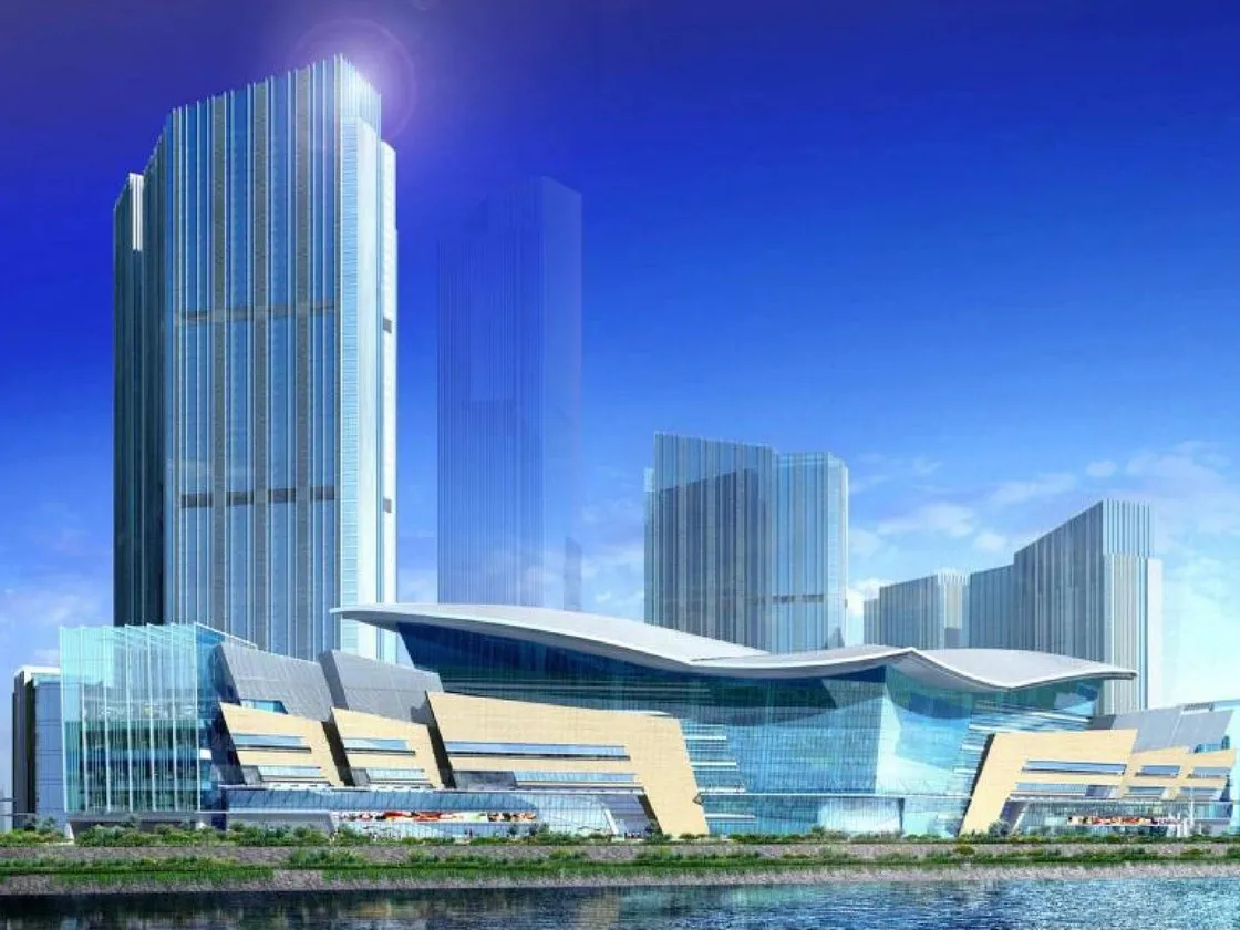
Hanart engineers review a parametric curtain wall BIM model during weekly coordination with the architect and structural consultant.
Why BIM is non-negotiable for complex facades
Traditional 2D documentation — elevations, sections and detail sheets — fails when architects introduce curvature, varying panel sizes, or point-supported structural glass. Coordinates cannot be inferred from elevations, joint geometry becomes ambiguous in three dimensions, and clashes between primary structure and facade bracketry remain invisible until steel arrives on site. For a free-form facade with 4,000 unique panels, manual 2D dimensioning would consume months and guarantee conflict.
Parametric facade modeling resolves this by encoding design rules. The architect defines surface geometry, the structural engineer sets grid constraints, and the facade engineer builds panel families with parametric relationships: panel width as a function of grid module, glass thickness as a function of wind load, bracket length as a function of structural offset. When the architecture changes, the model regenerates every dependent element. This is the only scalable method for maintaining geometric integrity across thousands of unique components.
The commercial case is equally compelling. BIM facade design at schematic stage typically reduces Requests for Information by 20 to 35 percent during construction documentation. Clash detection before fabrication identifies 40 to 60 percent of field conflicts that would otherwise require on-site remediation. On a 50,000-square-metre facade, eliminating just 2 percent of rework through early clash resolution can save USD 800,000 — far exceeding the incremental modeling investment.
The BIM workflow for curtain walls
A complete BIM curtain wall workflow spans seven phases with distinct deliverables that feed forward. Hanart coordinates this with the design team through weekly model exchanges.
Phase 1: Conceptual surface and grid rationalisation. The architect provides a Rhino or SketchUp massing model. Hanart imports it into Revit or Grasshopper and overlays the structural grid. Grid rationalisation divides the free-form surface into panel families that minimise unique types while respecting visual intent. For a recent airport terminal with a hyperbolic paraboloid roof, rationalisation reduced 3,800 unique panel types to 340 families by accepting 12-millimetre edge-gap variation — invisible at viewing distance but decisive for fabrication cost.
Phase 2: Parametric panel family development. Each panel family is modelled with fully parametric geometry: frame extrusions, glass build-up, gasket profiles, drainage channels, and pressure-plate geometry. In Revit these are curtain wall panel families with nested parametric components; in Grasshopper they are definitions that bake to layers for documentation. The parametric curtain wall model becomes a digital prototype of every physical panel.
Phase 3: Structural analysis integration. The facade model is exported to ETABS, SAP2000 or Robot for frame behaviour, and to Strand7 or Abaqus for complex bracket connections. Wind loads are applied per face zone, and deflections are checked against glass bite and sealant movement capacity. Results feed back as validated parameters — glass thickness, bracket size, anchorage layout — so the fabrication model has already passed engineering verification.
Phase 4: Thermal and energy modelling. Facade geometry is exported to IES VE, EnergyPlus or Ladybug-Honeybee for thermal simulation. U-values, solar heat gain coefficients, and condensation risk are calculated per panel type and orientation. Where condensation is predicted on metal frames in cold climates, thermal break geometry is adjusted parametrically. Thermal performance is certified before fabrication drawings are issued.
Phase 5: Clash detection and design coordination. The facade model is federated with structural, MEP and adjacent building models in Navisworks or Solibri. Hanart runs three formal clash-detection cycles: after schematic design, after design development, and after construction documentation. Each cycle produces a clash report with severity classification, responsible party, and resolution deadline. High-severity clashes affecting structural safety or waterproofing are resolved before the next exchange.
Phase 6: Fabrication-ready detail extraction. Once the model is clash-free and structurally validated, it becomes the fabrication source of truth. Glass cutting lists export with every pane dimension, thickness, coating, and hole location. Aluminum extrusion lists carry CNC-ready coordinates. Sealant joint geometries become detail drawings with dimensional callouts. The traditional shop drawing phase, historically six to ten weeks, compresses to two to three weeks.
Phase 7: Installation simulation and sequencing. Crane reach envelopes, panel lifting orientations, and crew access paths are simulated in Navisworks Timeliner or Synchro. For a 200-metre tower, simulation may reveal that standard hoisting is blocked by a transfer truss on levels 15 and 30, requiring revised sequencing and temporary support design. Identifying this in the model eliminates programme delay and safety risk.
Software stack and interoperability
No single platform satisfies every facade BIM requirement. Hanart operates a multi-tool stack with disciplined interoperability protocols.
Autodesk Revit with Dynamo. Revit is the primary documentation platform, being the native environment of most architects and structural engineers. Hanart develops custom Dynamo scripts for grid generation on doubly-curved surfaces, panel family instantiation, and parameter population from Excel schedules. Revit's curtain wall toolset handles 70 percent of standard unitised and stick-built systems; for free-form geometry, Revit serves as the documentation host while Rhino handles primary surface modeling.
Rhinoceros with Grasshopper. For complex curvature, parametric optimisation and panel rationalisation, Grasshopper definitions encode facade geometric logic: surface domain division, panel planarity optimisation, and structural grid alignment. The Kangaroo physics solver simulates cable-net and membrane behaviour under load. Geometry bakes to Rhino layers and imports into Revit via Rhino.Inside or IFC exchange.
Tekla Structures. For steel-intensive systems — steel curtain walls, cable-net supports, large-span atria — Tekla provides superior connection modeling and CNC output. The steel sub-model exports as IFC and federates into the master Revit model for coordination.
Navisworks Manage. Navisworks aggregates all discipline models for clash detection, walkthrough review, and 4D construction simulation. Hanart maintains a clash matrix with tolerance rules: 5-millimetre hard clash for structural connections, 25-millimetre clearance for maintenance access, 10-millimetre soft clash for panel joints.
IFC interoperability and LOD definitions. Model exchange uses IFC4 with defined Level of Development per milestone. LOD 200 for schematic: massing and grid. LOD 300 for design development: panel families with generic geometry. LOD 350 for construction documentation: fabrication-level detail, materials, connections. LOD 400 for fabrication: CNC-ready geometry. LOD 500 for as-built: installed conditions with maintenance data. These definitions prevent the common failure of visually impressive models that lack fabrication precision.
Clash detection and coordination
Clash detection is the quality gate that separates BIM visualization from BIM engineering. A model that looks correct but contains unresolved spatial conflicts breeds false confidence. Hanart operates a three-tier facade clash detection protocol.
Tier 1: Hard clashes. Physical intersections between facade components and other elements. The most frequent is bracket-to-concrete edge beam conflict, where the anchorage zone overlaps reinforcement or formwork ties. Another common clash is MEP penetration through spandrel panels where duct routing lacked facade coordination. Hard clashes are critical and must be resolved before fabrication release.
Tier 2: Clearance clashes. Proximity violations where components do not intersect but violate minimum clearances. Examples include panels positioned too close to fireproofing spray, blocking future re-glazing access, or operable windows that cannot fully open due to adjacent balcony slabs. These are classified as major and resolved before installation.
Tier 3: Workflow clashes. Sequence conflicts where trades compete for the same space simultaneously — installation crew versus scaffolding dismantling crew competing for crane time and roof access. Identified through 4D simulation, these are resolved through schedule adjustment.
Coordination follows a structured cadence. Weekly internal clash-review sessions filter automated reports, eliminating false positives. Bi-weekly multidisciplinary meetings with the architect, structural engineer and MEP consultant assign responsibility and agree deadlines. Critical clashes escalate to the project director with technical solutions and cost-impact estimates. This governance ensures clash detection produces decisions, not just data.
The economic impact is measurable. On a recent 80,000-square-metre tower in Southeast Asia, clash detection identified 340 clashes before fabrication: 120 hard bracket conflicts, 85 MEP penetrations, and 135 clearance issues. Resolving these in the model cost approximately USD 45,000. The estimated on-site remediation cost would have exceeded USD 620,000. The return on modeling investment was fourteen to one.
Fabrication-ready detail extraction
A well-constructed parametric model at LOD 400 replaces traditional shop drawings as the primary fabrication instruction. Hanart's extraction workflow generates four data streams directly from the verified model.
CNC cutting data. Aluminum profiles export from Revit or Tekla as DXF or STEP files, imported directly into CNC machining centres. Each profile carries instance-specific cutting length, drilling coordinates, and milling paths. For a unitised panel with 12 aluminum components, manual dimensioning historically required four hours per panel. Direct CNC extraction reduces this to 15 minutes of program verification. Over 5,000 panels, the saving is 1,200 engineer-hours.
Glass size schedules. Every glass pane exports as a structured schedule: width, height, thickness, coating specification, hole diameter and location, edge treatment, and unique panel identifier. Transmitted directly to the processor, this eliminates manual transcription from drawing to spreadsheet. Error rates drop from 2–3 percent to below 0.3 percent.
Sealant and gasket detail drawings. Joint geometries extract from the model as section views with automatic dimensioning. Structural silicone joint width and bite dimensions derive from model geometry and movement analysis, output as detail sheets with 3D isometric views. Gasket profiles match from model parameters to manufacturer standards, with exceptions flagged for custom extrusion. The result is geometrically consistent waterproofing detail.
Installation sequence animation. The 4D model generates installation animations for site crew briefing. Each panel is colour-coded by phase, crane pick is simulated with sling geometry, and temporary supports are visualised. For atrium structures installed from mobile platforms, animations identify reach limitations before the first lift. Site crews report that visual briefings reduce installation errors by 30 percent compared to paper-based method statements.
Hanart's BIM capability
Hanart established its BIM modelling team in 2018, recognising that contractors unable to deliver digital coordination would be excluded from the most demanding projects. The team now comprises 12 specialists: six facade modellers, three structural integration engineers, two clash-detection coordinators, and one digital fabrication programmer. All hold Autodesk professional certifications; four hold advanced Grasshopper credentials.
The portfolio spans the full complexity range. Standard high-rise unitised towers are modelled in Revit with Dynamo automation, delivering LOD 350 within three weeks of contract award. Double-skin facades with active ventilation require MEP-integrated modeling and Navisworks coordination, typically delivering LOD 350 within five weeks. Free-form cultural buildings need Rhino-Grasshopper parametric modeling followed by Revit documentation, with delivery timelines of six to eight weeks.
A representative project is the Qingdao Grand Theatre, where Hanart delivered a 12,000-square-metre free-form steel-and-glass facade. The BIM model contained 1,400 unique panel families, 2,800 bracket types, and 4,600 connection nodes. Clash detection resolved 210 hard clashes before fabrication. Glass cutting lists exported directly to the processor achieved zero dimensional errors on the first batch. The installation animation briefed a 40-person crew, and panel installation completed 18 days ahead of programme.
Hanart offers digital-twin handover. The as-built model is updated with as-fabricated dimensions, sealant batch numbers, glass certificates, and photographic documentation per panel. This digital twin becomes the foundation for maintenance, re-glazing and renovation. For owners with 25-year maintenance horizons, it is a more valuable deliverable than the physical product alone.
BIM capability is now a prequalification criterion on international tenders above USD 10 million contract value. Hanart's BIM 360 coordination protocol, developed across 30 projects since 2018, meets execution plans required by European, Middle Eastern and Southeast Asian project managers. The Revit family library contains over 400 curtain wall panel types, 150 bracket families, and 80 structural connection templates.
Get Hanart's BIM project portfolio and Revit family library
Request our BIM capability statement, including case studies from free-form cultural buildings, high-rise unitised towers and double-skin facades. Our team can also provide sample Revit families and a parametric workflow demonstration for your project geometry.
You may also like: