
Point-Supported Glass & Cable-Net Systems: Structural Transparency Without Visual Framing
Point-supported glass and cable-net facades represent the extreme end of structural transparency. By eliminating visible framing and relying on spider fittings, tension rods and cable geometries, these systems create the illusion of glass suspended in mid-air. The engineering behind that illusion is anything but simple.
Published 8 October 2026 — Hanart Facade Engineering Team
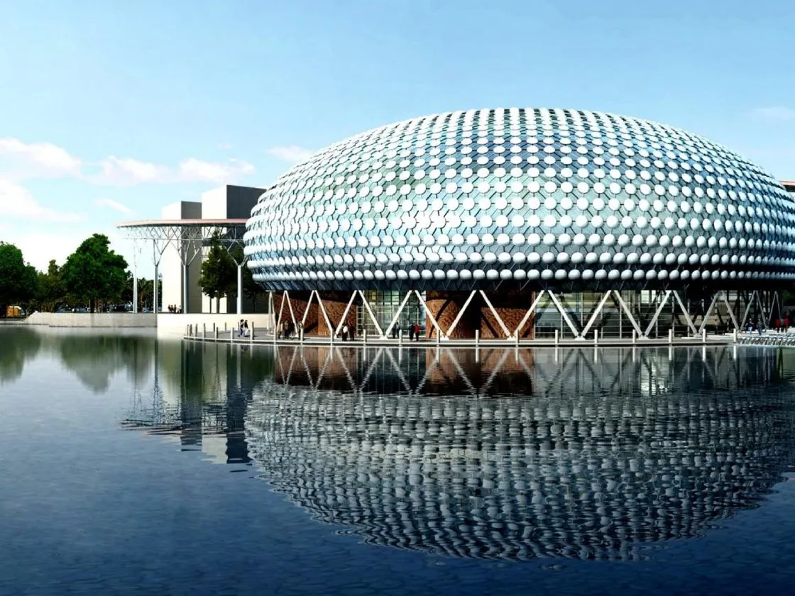
The aesthetic of disappearance: why architects choose point-supported
The fundamental promise of a point-supported facade is the disappearance of structure. Where a conventional curtain wall divides the visual field with mullions, transoms and silicone joints every 1.5 metres, a point-supported system presents an uninterrupted sheet of glass held only by discrete mechanical connections at the corners. The result is a sense of volume, lightness and suspension that no framed system can replicate.
Architects specify point-supported glazing for spaces where transparency is the architectural statement itself: atriums in corporate headquarters, entrance lobbies of museums, airside curtain walls at airports, and ceremonial halls where the boundary between interior and landscape is deliberately dissolved. The National Centre for the Performing Arts in Beijing and the Louvre Pyramid are the most celebrated examples; the same principle appears in hundreds of commercial and institutional buildings where the client demands that the envelope become invisible.
From an engineering perspective, however, invisibility imposes severe constraints. Every load that a conventional frame carries horizontally and vertically must now be transferred through discrete point connections into a network of cables, rods or glass fins. The tolerance for error drops to millimetres. The cost of a failed seal is not a minor leak — it is a catastrophic drop in performance that may require panel replacement.
Spider fittings and glass connection engineering
The spider fitting — so named for its radial arms — is the heart of the point-supported system. Hanart fabricates and sources fittings in four standard configurations, each suited to a different structural and visual condition:
- Four-arm spider. The standard configuration for interior grid intersections, transferring loads from four adjacent glass panels to a single node. Typically used in 2×2 m to 3×3 m grid layouts where the glass spans are regular and the visual density of the fitting is acceptable.
- Three-arm spider. Used at the boundaries of a glass field or at triangular grid intersections, where one direction terminates and the fitting must resolve an asymmetric load path.
- Two-arm spider. Employed along continuous edges — for example, where a glass roof meets a vertical wall — to transfer in-plane tension without introducing unnecessary visual weight at every node.
- Single-arm spider (cantilever bracket). The most visually minimal option, used where a panel is supported from one edge only or where an oversized monolithic panel requires discrete edge restraint rather than corner support.
Glass drilling geometry is governed by strict empirical rules that have emerged from two decades of failure analysis. The drilled hole diameter is typically 30–50 mm for 12–19 mm thick glass. The edge distance — from the hole centre to the glass edge — must be no less than 2.5 times the glass thickness; for a 15 mm panel, that means 37.5 mm minimum. Hole spacing along an edge follows similar rules: centres should be separated by at least 4× thickness to prevent stress concentration and crack propagation between adjacent holes. All glass must be fully tempered, and for point-supported applications Hanart insists on heat-soak testing to reduce the spontaneous nickel-sulphide breakage rate below 0.01%.
The fitting head itself comes in two variants: flush-head and countersunk. Flush-head fittings sit recessed into a countersunk hole, presenting a flat surface that is easier to clean and less visually obtrusive. Countersunk fittings protrude slightly, offering simpler installation and better tolerance for angular misalignment. Hanart recommends flush-head for all atrium and lobby applications where the fitting is viewed from both sides, and countersunk for external facades where weather sealing takes priority over visual minimalism.
All spider fittings are manufactured from 316-grade stainless steel, cast or forged depending on the arm geometry, and finished to either mirror polish, satin matte or PVDF fluorocarbon coating to match the architectural specification. The investment-cast process is preferred for complex arm intersections because it produces finer grain structure and better fatigue resistance than sand casting.
Laminated glass for point-supported applications
Point-supported glass must be laminated. The reason is not structural redundancy in the conventional sense — it is safety. If a monolithic tempered panel breaks at a point-support node, the entire panel disintegrates into small cubes and falls immediately. A laminated panel, even if both lites shatter, retains its geometric integrity because the interlayer holds the fragments in place until replacement can be arranged.
The choice of interlayer is critical. Conventional PVB (polyvinyl butyral) has served the industry for decades, but its shear modulus is low — approximately 0.5 MPa at 20°C. Under wind load, the two glass lites act almost independently, and the composite panel stiffness is barely greater than a single lite. SGP (SentryGlas Plus, an ionoplast interlayer) has a shear modulus roughly 100 times higher — around 50 MPa — which means the two lites behave as a true composite beam. The practical consequence is that SGP-laminated panels can span significantly farther, or carry higher loads, with the same total thickness.
For point-supported applications, Hanart specifies SGP for all panels exceeding 2.5 m in any dimension, and for all overhead glazing regardless of span. The maximum reliable panel size with PVB interlayer is approximately 2.5 m × 5 m; with SGP, panels of 3 m × 8 m have been successfully installed in cable-net atriums, subject to project-specific structural verification. The additional material cost of SGP — typically 30–40% over PVB — is recovered through reduced glass thickness or reduced support density.
All laminated glass for point-supported work receives heat-soak treatment after tempering. The process — holding the glass at 290°C for several hours — accelerates the expansion of nickel-sulphide inclusions, causing potentially dangerous panels to break in the factory rather than in service. Hanart's specification requires a post-heat-soak spontaneous breakage rate below 0.01%, verified by lot sampling.
Cable-net and tension rod systems
Where the glass field is too large for glass fins or where the architect demands the absolute minimum of visible structure, cable-net and tension-rod systems provide the supporting geometry. These are tensile structures: every element works in tension, and the stiffness of the system comes from pre-tension, not from the bending resistance of the members.
Pre-tension design follows a simple rule: the initial tension in each cable is set at 15–25% of its minimum breaking load (MBL). Below 15%, the cable may go slack under reverse wind suction, producing unacceptable deflection and possible glass contact. Above 25%, the safety margin against accidental overload — snow, maintenance access, dynamic amplification — becomes uncomfortably narrow. For a 12 mm diameter stainless-steel cable with an MBL of 120 kN, Hanart typically designs for 18–22 kN initial tension, verified by load-cell measurement during installation.
Deflection control is specified as a fraction of span: typically L/50 for cable-net systems where the glass panels are rigid and can tolerate some frame movement, and L/100 for tension-rod systems where the rods are stiffer and the architectural tolerance is tighter. For a 20 m span, L/50 equals 400 mm of maximum sag under design wind load — a visibly large displacement that the glass grid must accommodate through articulation at the spider nodes.
Cable-net geometries fall into three categories:
- Flat cable-net. Cables run in two orthogonal directions, pre-tensioned against a stiff boundary frame. The simplest and most common geometry, suitable for rectangular atriums and flat skylights where the supporting structure above is a regular grid of beams.
- Curved cable-net. Cables follow a doubly-curved surface — synclastic or anticlastic — to create a three-dimensional glass roof. The curvature provides geometric stiffness, reducing the required pre-tension and cable diameter for the same span. Design and fabrication are significantly more complex; every cable length and every glass panel is unique.
- Single-direction tension cables. Used where the glass is supported primarily in one direction — for example, a vertical glass wall hung from a roof beam, with horizontal cables providing wind resistance only. The vertical cables carry gravity; the horizontal cables carry wind. Each system is designed independently.
The boundary structure is the most frequently underestimated element of a cable-net design. The cables exert large concentrated forces at their anchor points: a 20 m span with 20 kN pre-tension and 15 kN wind load produces an anchor reaction of 35–45 kN per cable. The boundary beam must be engineered as a primary structural element, not as a secondary facade frame. Hanart has encountered multiple projects where the structural engineer initially sized the boundary beam for conventional curtain wall loads, only to discover during facade detailing that the cable reactions required a section three times larger.
Cable materials divide into two classes: stainless-steel cables (7×7 or 1×19 construction, 316 grade) for interior and coastal applications where corrosion resistance is essential; and high-strength steel cables (galvanised or zinc-aluminium coated, minimum breaking strength 1570–1860 MPa) for large-span exterior applications where the diameter must be minimised for visual reasons. The latter require rigorous corrosion protection at all terminations and anchorages.
Glass fins and steel frames for large spans
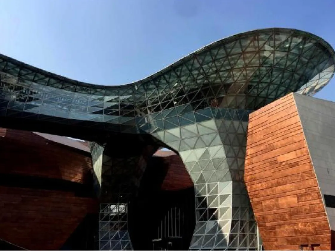
Not every point-supported facade requires cable-net technology. For medium spans — 6 m to 15 m — glass fins provide a visually elegant and structurally efficient alternative. A glass fin is a vertical laminated glass beam, typically 15–25 mm thick, that stands perpendicular to the facade plane and carries the vertical dead load of the glazing above. The point-supported panels are attached to the fins through spider fittings, and the fins themselves are anchored at floor level.
The advantage of glass fins is their own transparency: viewed from the oblique angles typical of atrium circulation, a 19 mm glass fin is barely visible. The disadvantage is their structural depth: a glass fin must be 1.5 to 2 times deeper than an equivalent steel beam for the same span and load, and the connection between fin and floor slab requires careful detailing to avoid stress concentration at the base.
For spans beyond 15 m, or where the facade geometry is too complex for flat glass fins, steel trusses and space frames become necessary. Hanart has integrated point-supported glazing with tubular steel trusses (circular hollow sections, 100–250 mm diameter), space-frame node systems, and even cable-stayed masts for the largest atrium roofs. In every case, the principle is the same: the primary structure resolves the spans, and the point-supported glazing provides the weather envelope with minimal visual interruption.
Structural analysis and load paths
The structural behaviour of a point-supported facade is fundamentally different from a framed curtain wall, and the analysis must reflect that difference. Two load paths dominate:
Out-of-plane loads — primarily wind pressure and suction, plus seismic action where applicable — are transferred from the glass panels to the spider fittings, from the fittings to the cable-net or steel frame, and from there to the primary building structure. Because the glass is point-supported rather than line-supported, each panel acts as a two-way plate, and the load distribution to the four corners is non-uniform. Corner stress concentrations must be checked with finite-element models that capture the local stress field around the drilled hole.
In-plane loads — gravity, temperature expansion, and accidental impact — are carried by vertical supports (glass fins, tension rods or cable drops) or by suspended top anchors. Temperature movement is a particular concern: a 6 m glass panel experiences 3.6 mm of thermal expansion between 0°C and 40°C. If the support system does not allow in-plane movement, the panel will induce buckling or cracking in itself or its neighbours. Hanart designs all point-supported systems with deliberate in-plane articulation at every spider node.
Non-linear analysis is mandatory for cable-net systems. Cables have no bending stiffness: their resistance to load comes entirely from geometry and tension. Under wind suction, a cable may slacken; under pressure, the net may deflect into a new equilibrium shape that is not predictable by linear elastic methods. Hanart uses iterative geometric non-linear analysis for all cable-net designs, with large-displacement formulation and cable-only elements that correctly model tension-only behaviour.
Vibration control is often overlooked in point-supported design. Lightweight cable-net systems can be excited by vortex shedding in steady wind, producing visible oscillation that alarms building occupants. Hanart specifies damping measures — tuned mass dampers, viscoelastic cable dampers, or aerodynamic fairings — for all cable-net spans exceeding 25 m, and verifies the natural frequency of the system against the expected wind spectrum at the project site.
Weather performance and edge sealing
Point-supported systems present a unique waterproofing challenge. In a conventional curtain wall, every glass edge is captured in an aluminium frame with dual-seal gaskets and a drained cavity. In a point-supported system, the glass edges are exposed to the weather except where they meet an adjacent panel. There is no frame to hide imperfections; every joint must be individually sealed, and the seal must perform for the design life of the building.
Hanart specifies high-modulus silicone structural sealant (HMSS) for all point-supported joints between glass panels. The sealant must meet ASTM C1184 or EN 15651-2 requirements, with a movement capability of ±25% and proven adhesion to glass and stainless steel under UV exposure. The joint width is designed for 6–10 mm, with a depth-to-width ratio between 0.5 and 1.0 to ensure proper curing and stress distribution.
Condensation control is equally critical. The absence of a thermally broken frame means that the interior surface of the glass near the point-support nodes can become cold bridges. In high-humidity environments — swimming pools, tropical atriums, botanical gardens — Hanart specifies heated glass or cavity ventilation to prevent condensation at the nodes, and details drip edges to manage any incidental moisture.
Hanart's point-supported project experience
Hanart has delivered point-supported and cable-net facade systems for over 80 projects since 2005, ranging from 200 m² entrance canopies to 12,000 m² airport atriums. The majority are in the 1,000–4,000 m² range — commercial lobbies, museum entrance halls, and corporate atriums where the architectural statement justifies the structural complexity.
Spider fitting procurement is a critical quality control point. Hanart maintains dual-source relationships with both domestic Chinese foundries (for cost-sensitive projects) and European manufacturers such as Dillmeier and seele (for projects requiring EN 1090-3 traceability and mill-test certification). Every fitting lot is inspected for dimensional tolerance (±0.2 mm on arm lengths), surface finish consistency, and load-bearing verification through sample pull-testing to 1.5× design load.
Site installation precision is the phase that separates successful point-supported projects from problematic ones. Hanart's installation teams use total-station surveying to establish the cable-net geometry to ±3 mm absolute tolerance before any glass is lifted. Every spider fitting is installed with rotational adjustability — typically ±5° in two axes — to accommodate the inevitable tolerance stack-up between structural steel, cable-net, and glass fabrication. The adjustment range is verified during mock-up installation and locked after final alignment.
Get Hanart's point-supported glass facade proposal and structural calculation
If your project involves an atrium, lobby, skylight, or any space where visual transparency is paramount, a point-supported or cable-net facade may be the only solution that satisfies the architect's intent. The engineering is complex, the tolerances are tight, and the procurement requires a contractor with both structural design capability and precision installation experience.
Hanart offers a complimentary preliminary structural assessment for point-supported facade enquiries. The assessment includes: load path definition, preliminary cable or rod sizing, glass thickness recommendation, boundary reaction summary, and an indicative budget band — delivered within five working days and under no obligation.
Request Point-Supported Facade Proposal Explore Point-Supported Systems →
Related: Glass Curtain Wall Systems · Curved & Free-Form Curtain Walls · Seismic Design for Curtain Walls