
Curtain Wall Structural Design: Loads, Deflection & Engineering Checks
A curtain wall earns its place in the building's structure through calculation: wind pressures, snow and seismic loads, thermal movement and inter-storey drift all flow through the mullion, the anchorage and the glass edge. This article explains the load logic, the deflection limits and the engineering checks that turn a facade sketch into a buildable, code-compliant system.
- Hanart Engineering Blog
- 9 October 2026
- 5 field photographs
Photographs from the Programme
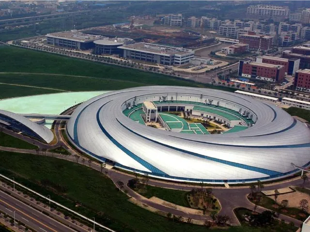
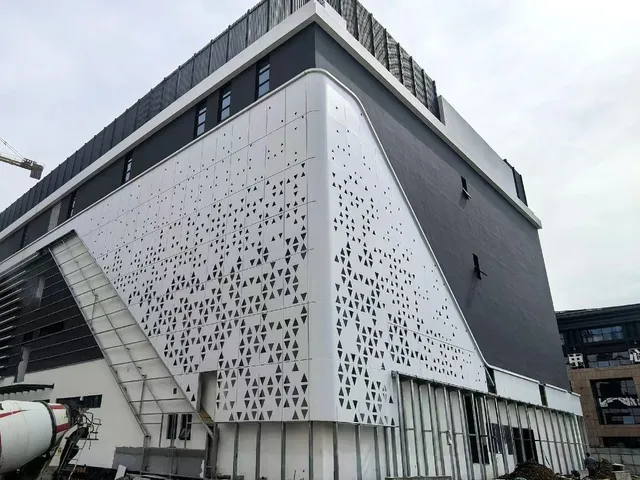
Real Hanart site and factory photography — the discipline described below, seen in the field.



The Engineering View
Structural design starts in the model: the mullion grid, anchorage points and glass zones are load-mapped before any profile is cut. The Load Path: Nothing in a Curtain Wall Is Decorative
Structural design starts in the model: the mullion grid, anchorage points and glass zones are load-mapped before any profile is cut.
Every curtain wall component carries load along a defined path: wind pushes the glass, the glass edge transfers the load through gaskets or silicone into the mullion flange, the mullion spans between floor slabs and delivers the load through steel brackets to the structure, and the brackets transfer it into the slab edge. Interrupting any link in that chain — a soft gasket, an undersized screw, a bracket with insufficient edge distance — reroutes the load somewhere it was never designed to go, and that is how facades fail.
The calculation defines the section; the machine holds it: profiles are machined to ±0.5 mm so the design assumptions survive to site. Load Case 1: Wind Load
The calculation defines the section; the machine holds it: profiles are machined to ±0.5 mm so the design assumptions survive to site.
Wind is the dominant lateral load on most curtain walls. The design wind pressure derives from the local code — in China GB 50009, in the US ASCE 7, in Europe EN 1991-1-4 — and combines a reference (or basic) wind speed, terrain roughness, height exposure, topography, and the building's shape and pressure coefficients. Reference wind speeds can reach 40–55 m/s in typhoon zones, producing design pressures of 3–5 kPa or more on exposed facades; corner zones attract higher local suction and are a classic failure location.
Load Case 2: Snow, Seismic and Thermal Loads
Sloped glazing and skylights add snow and live loads on the glass plane, which are checked against the glass strength and the rafter or purlin system. Seismic loads differ from wind in direction and character: the facade must follow the building's inter-storey drift without losing glass edge contact or anchorage integrity. Codes express this as a drift capability requirement — commonly ±18–±25 mm for unitized systems (AAMA 501.4) — rather than a strength check, because the facade is designed to move with the frame, not to resist the earthquake directly. The seismic design article develops the drift story in detail.
Thermal load is the invisible third force: aluminum expands roughly 23 µm per metre per 10°C. On a 50-metre mullion run, a 60°C seasonal range is over 6 mm of total movement that must be absorbed by expansion sleeves, slotted holes and correctly pre-set joints — if the design forgets thermal movement, the facade will design it back in as cracks, buckled gaskets and popped sealants. Hanart's shop drawings mark every thermal break point and movement allowance explicitly, because it is the detail that never shows in the renderings but always shows up in warranty claims.
Stage by Stage
Want the Structural Design Checked Properly?
Hanart calculates every facade to code — GB 50009, ASCE 7 or EN 1991-1-4 — verifies with mock-up testing and delivers the calculation package with the tender. Email bob@hanartfacade.com or call +86-21-5106 1751.
Specifications & Standards Referenced
- GB 50009
- GB/T 21086
- EN 1991-1
- AAMA 501
Traceability & Sources
- Read the full source article: Curtain Wall Structural Design: Loads, Deflection & Engineering Checks — source page
- Project file: National Indoor Stadium, Beijing — Large-span metal roof and curtain wall on the 2008 Olympic programme — Luban Prize the same year.
- Performance Testing: What the Numbers Prove — related note
- Facade Engineering: First on the Critical Path — related note
- Facade Standards Hub — test methods cited across the library
Have a project with this scope?
Send drawings, get a facade proposal in 24 hours — engineered, fabricated and installed by one contractor, one responsibility.