
Point-Supported Glass & Cable-Net Systems: Structural Transparency Without Visual Framing
Point-supported glass and cable-net facades represent the extreme end of structural transparency. By eliminating visible framing and relying on spider fittings, tension rods and cable geometries, these systems create the illusion of glass suspended in mid-air. The engineering behind that illusion is anything but simple.
- Hanart Engineering Blog
- 8 October 2026
- 5 field photographs
Photographs from the Programme
Real Hanart site and factory photography — the discipline described below, seen in the field.
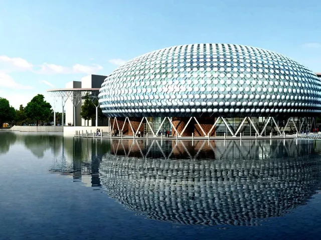
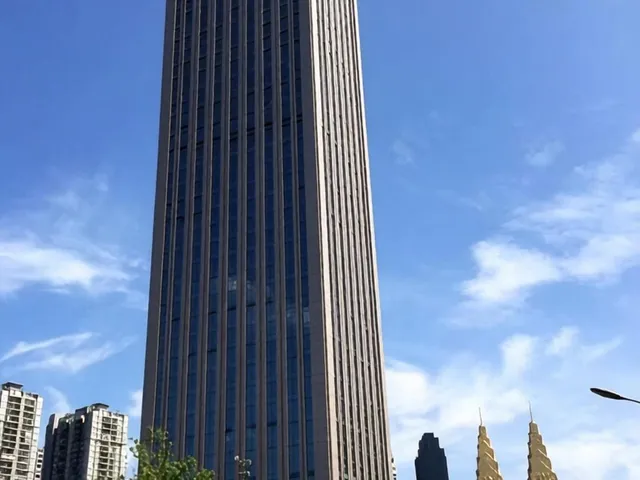
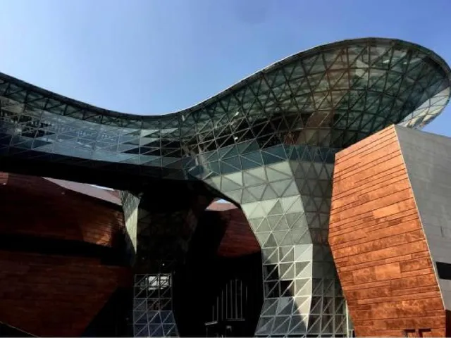
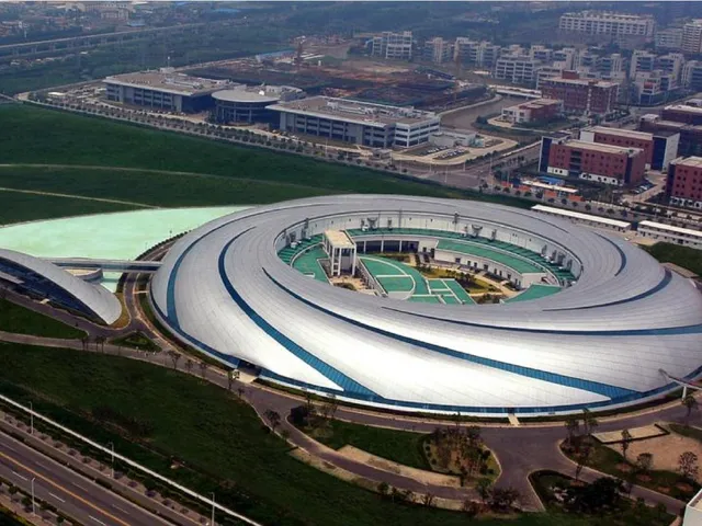
The Engineering View
The aesthetic of disappearance: why architects choose point-supported
The fundamental promise of a point-supported facade is the disappearance of structure. Where a conventional curtain wall divides the visual field with mullions, transoms and silicone joints every 1.5 metres, a point-supported system presents an uninterrupted sheet of glass held only by discrete mechanical connections at the corners. The result is a sense of volume, lightness and suspension that no framed system can replicate.
Architects specify point-supported glazing for spaces where transparency is the architectural statement itself: atriums in corporate headquarters, entrance lobbies of museums, airside curtain walls at airports, and ceremonial halls where the boundary between interior and landscape is deliberately dissolved. The National Centre for the Performing Arts in Beijing and the Louvre Pyramid are the most celebrated examples; the same principle appears in hundreds of commercial and institutional buildings where the client demands that the envelope become invisible.
Spider fittings and glass connection engineering
The spider fitting — so named for its radial arms — is the heart of the point-supported system. Hanart fabricates and sources fittings in four standard configurations, each suited to a different structural and visual condition:
Glass drilling geometry is governed by strict empirical rules that have emerged from two decades of failure analysis. The drilled hole diameter is typically 30–50 mm for 12–19 mm thick glass. The edge distance — from the hole centre to the glass edge — must be no less than 2.5 times the glass thickness; for a 15 mm panel, that means 37.5 mm minimum. Hole spacing along an edge follows similar rules: centres should be separated by at least 4× thickness to prevent stress concentration and crack propagation between adjacent holes. All glass must be fully tempered, and for point-supported applications Hanart insists on heat-soak testing to reduce the spontaneous nickel-sulphide breakage rate below 0.01%.
Laminated glass for point-supported applications
Point-supported glass must be laminated. The reason is not structural redundancy in the conventional sense — it is safety. If a monolithic tempered panel breaks at a point-support node, the entire panel disintegrates into small cubes and falls immediately. A laminated panel, even if both lites shatter, retains its geometric integrity because the interlayer holds the fragments in place until replacement can be arranged.
The choice of interlayer is critical. Conventional PVB (polyvinyl butyral) has served the industry for decades, but its shear modulus is low — approximately 0.5 MPa at 20°C. Under wind load, the two glass lites act almost independently, and the composite panel stiffness is barely greater than a single lite. SGP (SentryGlas Plus, an ionoplast interlayer) has a shear modulus roughly 100 times higher — around 50 MPa — which means the two lites behave as a true composite beam. The practical consequence is that SGP-laminated panels can span significantly farther, or carry higher loads, with the same total thickness.
Stage by Stage
Cable-net and tension rod systems
Where the glass field is too large for glass fins or where the architect demands the absolute minimum of visible structure, cable-net and tension-rod systems provide the supporting geometry. These are tensile structures: every element works in tension, and the stiffness of the system comes from pre-tension, not from the bending resistance of the members.
Glass fins and steel frames for large spans
Not every point-supported facade requires cable-net technology. For medium spans — 6 m to 15 m — glass fins provide a visually elegant and structurally efficient alternative. A glass fin is a vertical laminated glass beam, typically 15–25 mm thick, that stands perpendicular to the facade plane and carries the vertical dead load of the glazing above. The point-supported panels are attached to the fins through spider fittings, and the fins themselves are anchored at floor level.
Structural analysis and load paths
The structural behaviour of a point-supported facade is fundamentally different from a framed curtain wall, and the analysis must reflect that difference. Two load paths dominate:
Weather performance and edge sealing
Point-supported systems present a unique waterproofing challenge. In a conventional curtain wall, every glass edge is captured in an aluminium frame with dual-seal gaskets and a drained cavity. In a point-supported system, the glass edges are exposed to the weather except where they meet an adjacent panel. There is no frame to hide imperfections; every joint must be individually sealed, and the seal must perform for the design life of the building.
Hanart's point-supported project experience
Hanart has delivered point-supported and cable-net facade systems for over 80 projects since 2005, ranging from 200 m² entrance canopies to 12,000 m² airport atriums. The majority are in the 1,000–4,000 m² range — commercial lobbies, museum entrance halls, and corporate atriums where the architectural statement justifies the structural complexity.
Specifications & Standards Referenced
- ASTM C1184
- EN 15651-2
- EN 1090-3
Traceability & Sources
- Read the full source article: Point-Supported Glass & Cable-Net Systems: Structural Transparency Without Visual Framing — source page
- Project file: Zhejiang Art Museum, Hangzhou — Stone and point-supported glass envelope on a 2008 Luban Prize museum.
- SSG Curtain Wall: Structural Glazing Explained — related note
- Curtain Wall Structural Design: Loads & Deflection — related note
- Facade Standards Hub — test methods cited across the library
Have a project with this scope?
Send drawings, get a facade proposal in 24 hours — engineered, fabricated and installed by one contractor, one responsibility.